
— From the Mechanism of Sound Absorption to Thinsulate, and a Mazda Case Study on Reducing Road Noise —
Introduction
In recent years, interior quietness has become a key contributor to driving comfort. As engine noise has diminished and EVs have been proliferating, road noise (road roar)—sound generated by tire–road interaction, with a strong low-frequency content—has become more prominent. This article explains, in order: ① the theory of sound absorption, ② the high-performance absorber Thinsulate, and ③ a Mazda case study on road-noise reduction.
① How sound absorption works — the link between particle velocity and sound pressure
1) What sound is, and “energy dissipation”
Sound is a longitudinal wave that propagates through alternating compressions and rarefactions of air particles. Absorber materials convert the kinetic energy of this particle motion into heat via viscous friction and thermal conduction within the material, thereby dissipating acoustic energy. A useful analogy is tetrapods along a coastline: they do not “cancel” waves with an opposite wave; rather, they scatter and slow the flow, and the waves eventually “tire out.”
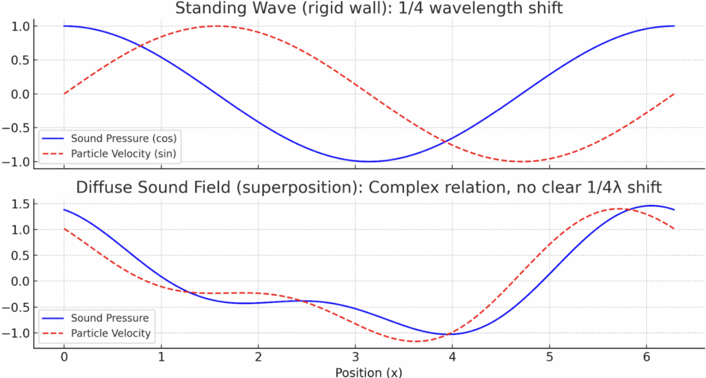
2) Standing waves at a rigid wall and the 1/4-wavelength shift
When a rigid wall reflects sound, a standing wave forms with the following properties:
- At the wall : sound pressure is maximum, particle velocity is zero
- At 1/4 wavelength from the wall : a velocity antinode (particle velocity maximum) and pressure minimum occur
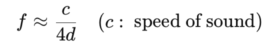
Therefore, placing porous absorbers where the particle velocity is large maximizes energy dissipation. For a target frequency (f) and an air gap (d), a useful rule of thumb is
3) Soft wall / no wall: in progressive waves, pressure and velocity are in phase
If the boundary is soft or effectively open, reflections are weak and a progressive wave dominates: sound pressure and particle velocity are in phase and the 1/4-wavelength relation does not hold.
4) Key point in three-dimensional fields (Z-direction)
In a quasi-diffuse field like a cabin, particle velocity in the short Z-dimension (height) tends to be small at low frequencies. Designs that create velocity in the Z-direction are therefore crucial for low-frequency absorption.
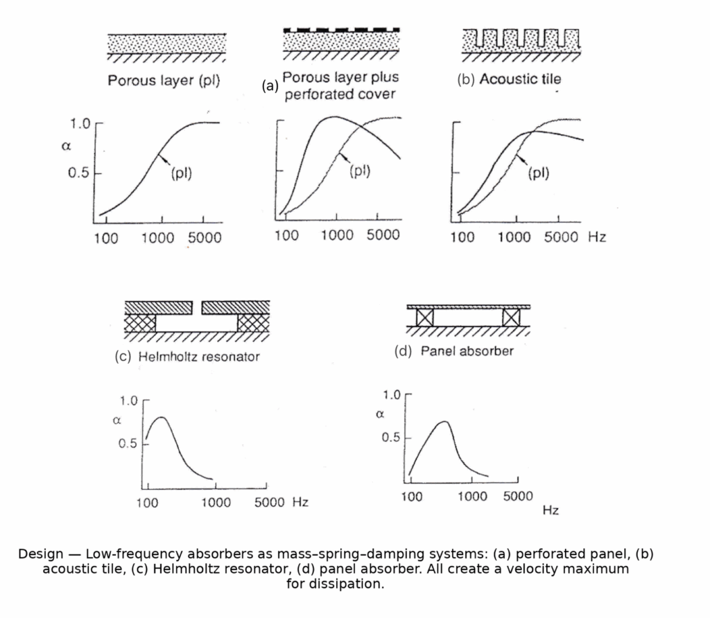
5) Low-frequency strategy: “two-layer” concept
Low frequencies have long wavelengths, so simply making absorbers very thick is often impractical. Instead, use two-layer / mass–spring–damper concepts to increase particle velocity and trigger dissipation:
- (a) Porous material plus perforated cover plate : air in the holes = mass, backing air cavity = spring, porous layer = damping
- (b) Acoustic tile : an array of small resonators yields a broader band
- (c) Helmholtz resonator : neck air = mass, cavity = spring; enables tuned low-frequency absorption
- (d) Panel absorber : panel = mass, backing cavity = spring ; absorbs over a surface area
All of these create velocity maxima via resonance, and damping turns that motion into heat.
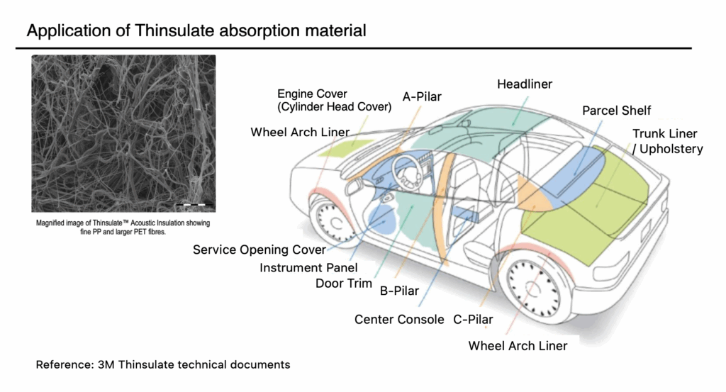
② Thinsulate — high-efficiency absorption from microfibers
Thinsulate (3M) is a non-woven made of very fine polyester fibers:
- Large specific surface area → more air–fiber contact → higher viscous losses
- High porosity → increased flow resistivity and thermal losses in the mat
As a result, Thinsulate achieves high mid-/high-frequency absorption while remaining thin and light, making it well-suited to headliners and door trims, among others.
③ Mazda case study — controlling road noise with a two-layer concept
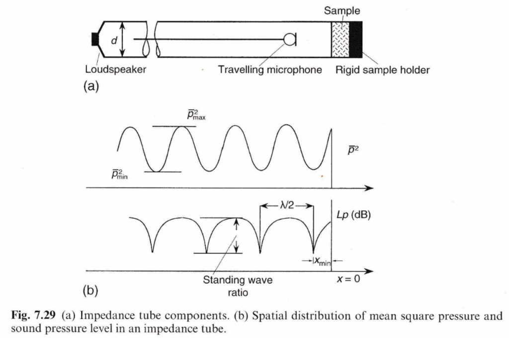
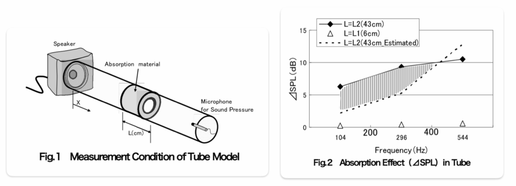
Experiment ①: Impedance-tube style test
Fig. 1: Tube setup — a speaker excites the tube and a microphone measures the pressure after the absorber (rigid termination). With L = 43 cm thickness, the measured absorption exceeded predictions. Interpreting the thick layer (together with the backing air) as quasi two-layer, the system likely forms low-frequency velocity antinodes, enhancing dissipation.
Fig. 2: Tube results — For 43 cm, the observed ΔSPL trends higher than the one-layer prediction, suggesting a two-layer effect not captured by a homogeneous model.
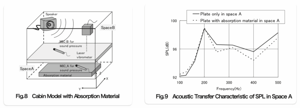
Experiment ②: Virtual two-layer cabin
Fig. 8–9: Extending the tube insight to a two-layer cabin model, Mazda evaluated surface particle velocity and sound pressure and observed SPL reductions around 250–500 Hz. The results verified that changes in the surface-velocity distribution drive low-frequency absorption.
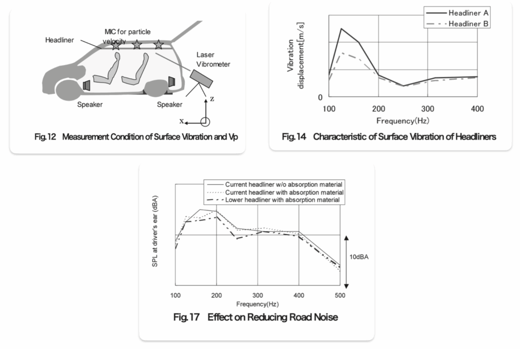
Vehicle application: road-noise reduction
Fig. 12, 14, 17: In the vehicle, a two-layer headliner was implemented. Measurements of particle velocity and laser vibrometer confirmed a reduction in road noise. A softer headliner (A), offering more mobility plus damping, produced higher surface particle velocity → more internal dissipation → lower SPL, outperforming a stiffer headliner (B) at low frequencies.
Conclusions
- Theory : With a rigid boundary, the λ/4 relationship holds; placing a porous absorber at the velocity antinode maximizes absorption. For low frequencies, however, the required thickness becomes impractical
- Design : Use two-layer / mass–spring–damper concepts to create particle velocity and target low frequencies with compact constructions
- Materials : Microfiber non-woven like Thinsulate are effective and lightweight for mid/high frequencies
- Validation : Mazda demonstrated that a soft boundary plus two-layer structure can generate Z-direction velocity and reduce road noise in the vehicle
References
- Frank Fahy, Foundations of Engineering Acoustics, Academic Press (2000)
- David Thompson, University of Southampton, ISVR, Noise and Vibration Control I (lecture notes)
- Naoko Yorozu, Chie Fukuhara, Takanobu Kamura, “Development of an Absorption Technique for Road Noise,” Mazda Technical Review (2008)
- 3M Thinsulate technical documents
Companion video
For a visual explanation, please see the accompanying video:
No responses yet